DESIGN OF FIXED BELAYING SYSTEMS ON FLAT ROOFS
The roof of each building requires periodic inspections, repairs and maintenance, and very often the service equipment and installations for the building are located on it. This involves both access to the roof and moving around it. The risk of falling is always significant, regardless of whether the work carried out lasted long or short.
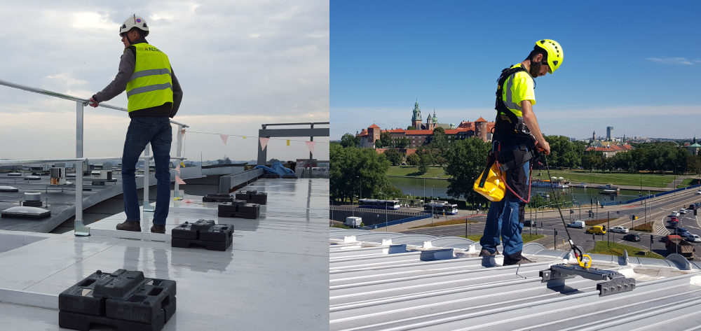
In the case of roofs, falls most often occur while staying at the edge of the roof, holes in the roofing, on roof elements of poor strength and at roof windows and skylights. The safety of persons staying on the roof can be ensured by the use of collective protection in the form of guardrails that will protect the areas at risk of falling (edge of the roof, skylights). An alternative to guardrails are fixed belaying systems, which are most often installed into the roof structural elements.
Types of fixed belaying system
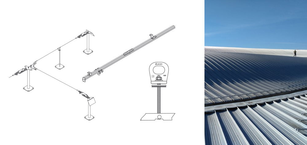
Fixed safety devices used on flat roofs include anchoring devices according to EN 795:2012 and CEN/TS 16415:2013: type A – anchoring points, type C – horizontal rope systems, type D – horizontal rail systems. In each case, they are permanently connected to the load-bearing elements of the building.
Properly designed and installed fixed anchoring systems allow for the proper solution of fall protection in such a way as to protect the worker both during the access route to the workplace and during the work itself.
The design of fixed belaying systems should be carried out by qualified personnel with substantial preparation for this type of work.
Design of fixed belaying systems
The selection and placement of anchoring components requires knowledge of the protective properties of the individual components, the performance requirements for anchoring equipment, knowledge of standards and regulations for fall protection. During the design phase, a risk assessment shall be carried out including the identification of the hazard zones where a potential fall may occur, with an estimate of the amount of free space at the site of the fall.
The next step is the analysis of the geometry and structure of the object, which determines the shape of the structure and the arrangement of the load-bearing elements of the object, which can be used to attach fixed anchoring devices.
An important element of the design process is to take into account the communication lines intended for movement on the roof, the areas of work including its type, the number of people performing work simultaneously, as well as the frequency of the work.
The hazards associated with falling on flat roofs include: falling through the edges of the roof, skylights, smoke flaps, pendulum when falling from external corners, hitting the ground from low objects, hitting obstacles under the workplace.
Hazard zone
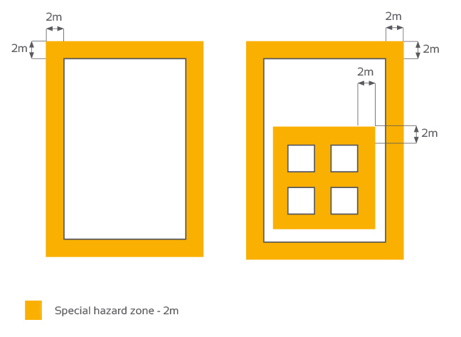
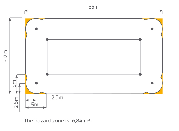
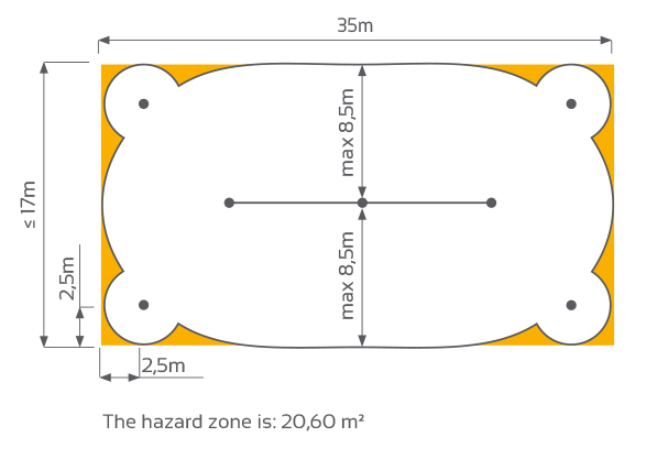
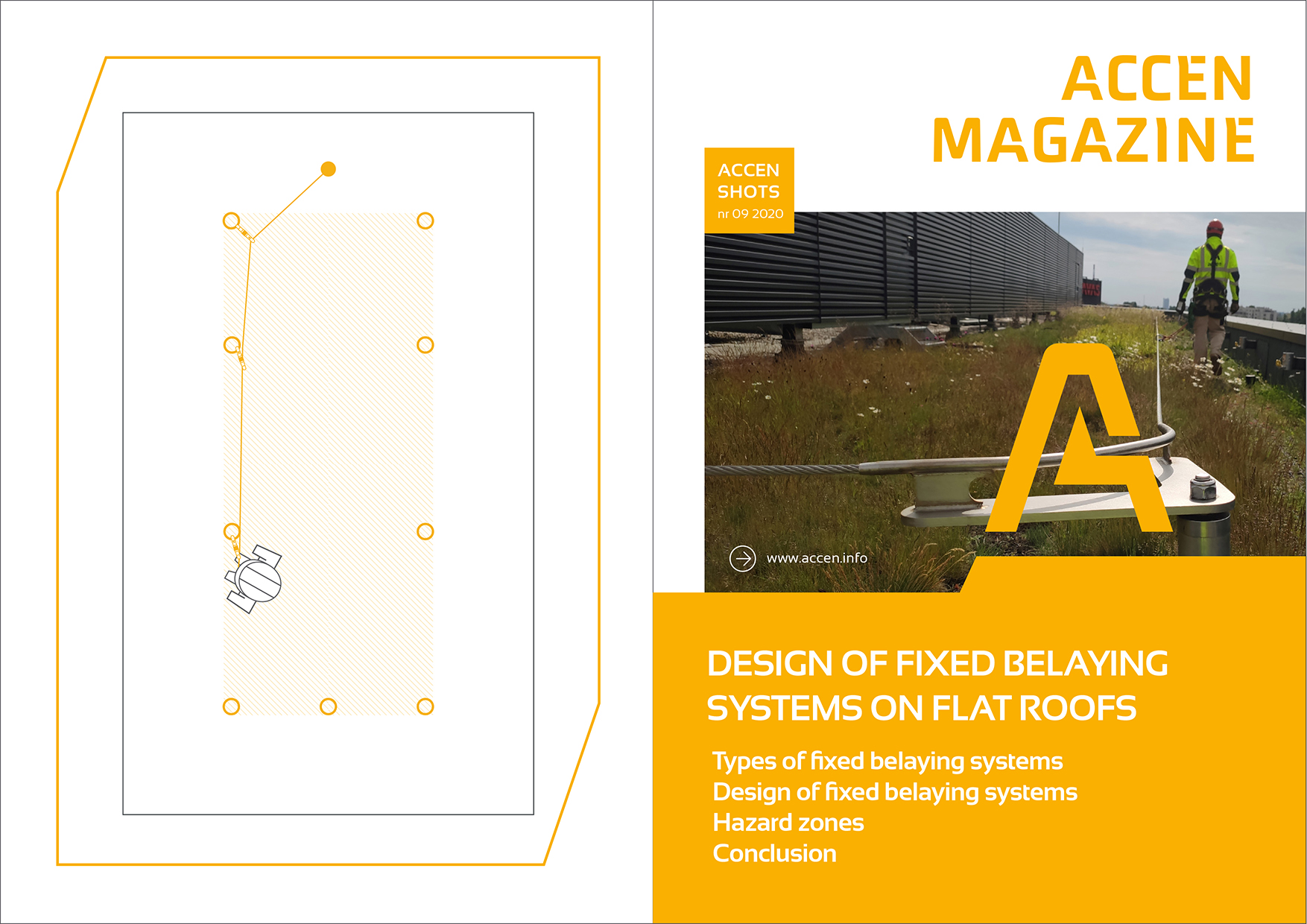
Flat roof surfaces are defined as hazard zones. Risk of falling may occur in relation to the edges of the roof, skylights or smoke flaps. In such cases, the area at a distance of up to 2m from the edge is a particularly high hazard zone. Therefore, the anchoring devices should be positioned around these zones.
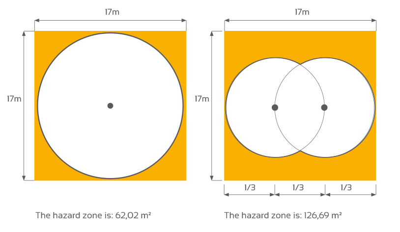
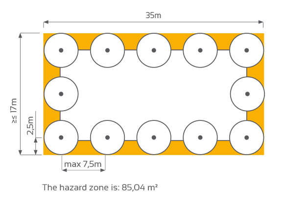
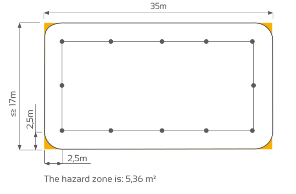
The colour yellow indicates the hazard zone and should be as small as possible.
Example 1
The correct selection and placement of anchoring devices is critical to safety.
Example 2 Securing the roof perimeter by means of belaying posts.
Example 3 Roof protection perimeter rope system.
Example 4 Roof protection perimeter rope system and anti-pendulum posts.
Example 5 Roof protection by a rope system in the ridge and anti-pendulum posts.
Risk of a pendulum fall
Another hazard is the risk of pendulum movement in the event of a fall at the outer corner of the roof. It is therefore important to consider the installation of anti-pendulum posts at safe distances.
Example 6 The following example shows the different lengths of free fall depending on the edge through which the fall occurs.
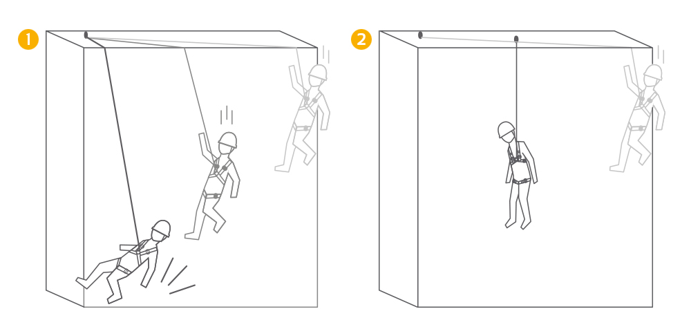
Pendulum effect when falling. No anti-swing anchor points.
2. The pendulum effect is neutralized thanks to the anti-swing anchoring point used.
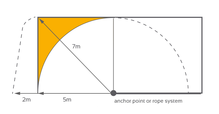
The distance of the protection post to the edge should not exceed 5 meters. On straight sections, the distance of the protection posts from the edge determines the length of the connecting and depreciating subassembly (e.g. guided type fall arrester with rope). The appropriate length can be adjusted freely and this means that the protection posts do not necessarily have to be at the same distance from the edge of the roof.
Example For a protection post distance of 5m from the edge of the roof, the length of the connecting and damping subassembly of the corner edge is approx. 7m, and the path of a free fall is at last 2m.
Example For a protection post distance of 10m from the edge of the roof, the length of the connecting and damping subassembly of the corner edge is approx. 14m, and the path of free fall about 2m.
By installing an additional anti-pendulum post at the point of intersection of the circle marked by the connecting rope with the diagonal, the free fall path is reduced to 1,2 m.
Fall from low objects
A great hazard is the possibility of falling from a roof with a small height (up to 6m). This is the so-called free fall path, i.e. the sum of the length of the connection to the belaying system, the extension of the energy absorber and the distance between the connection point in the safety harness and the worker’s feet. On low objects there is a risk of hitting the ground before the belaying system works. Therefore, on such objects, fixed belaying systems should be designed to limit the possibility of a fall. Safety is achieved by creating a system parallel to the edge of the roof at the shortest and fixed distance. In such a belaying system, it is important to use a connecting and damping subassembly of appropriate length, i.e. 0,5 m shorter than the distance from the point of connection to the roof edge. This excludes the risk of falling off the edge at all times.
Falling on obstacles below the workplace
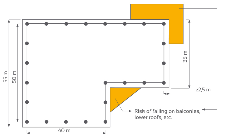
Also keep in mind objects located at different heights, which can pose a danger during a potential fall. The most common “obstacles” are lower roofs, outbuildings, ramp roofing, balconies, etc. As in the case of objects of low height, belaying systems should be designed to prevent the occurrence of a fall, the so-called “work in restaint”.
Conclusion
A fixed fall protection system can be installed on virtually any roof. The ideal solution from a technical and organisational point of view is to anticipate the appropriate anchoring elements already in the design phase of the building and to make them during construction. However, in the vast majority of cases it is technically feasible to install anchoring devices on existing buildings as well.
This Guideline is based on current legislation and standards for occupational safety at heights, taking into account European safety standards as well as good practice and recommendations from manufacturers of anchoring systems.
Significant indications were taken from the document “Planungsgrundlagen von Anschlageinrichtungen auf Dächern” prepared by the international group of experts D-A-CH-S in the field of safe working at heights.


